Introduction
 Since a couple of weeks I have 3 Pekin Bantam hens in my garden. Although it is not a big deal opening and closing the chicken coop door daily, it still is a fun little project to automate this. For example the coop automatically opens at sunrise and closes at sunset.
In my Home Assistant installation I’m already using the ESPHome integration for other small sensors in my home. So why not make use of ESPHome?
The total cost for this project is about 25 euros. I did recycle multiple parts of my old defective 3D printer, therefore I only needed new endstops and the stepper driver.
In the partlist I added the current (July 2022) prices from AliExpress. I will add a link to the products I *think* you can use, although they are slightly different then the ones I already had. See it as a global shopping guideline.
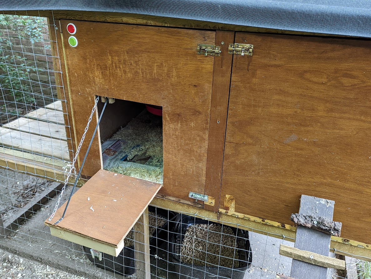
My chicken coop door is a drawbridge style door. With some adjustments this project can also be used for a sliding door. My first proof-of-concept build was a sliding door, until I realized that I didn’t have the required height…
Partlist
 This is the minimum amount of parts to get your own Home Assistant / ESPHome enabled chicken coop door.
Guess it is probably a bit over-engineered. But hey, it works 🙂
- NodeMCU v3 CH340 (3 euro)
- USB adapter + micro USB cable (5 euro)
- NEMA 17 stepper motor (10 euro)
- Stepper motor wire (Included with motor)
- Timing belt (1 euro)
Size: GT2-6mm, 1 meter - Timing belt gear (1,30 euro)
20 Teeth Bore 5mm, width 6mm - A4988 stepper driver (1 euro)
- 12V, 2A power supply + DC male connector (3,50 euro)
- Some counterweight attached to the timing belt
Optional / Nice to have
- Endstop (2x) (2,50 euro)
- Momentary button / push button (2x) I used a reset button with a 3D printed arcade button, but a premade button will also do fine)
- Chain, 1 meter
 The endstops are used to stop the stepper motor immediately when they are being pressed, even if the target or open_duration in the source code below aren’t met.
If you decide not to use endstops make sure to adjust the target and open_duration to match as closely as possible. This prevents the stepper motor from continuing spinning while the chicken coop door is already fully opened or closed.
The buttons are used to manually open or close the chicken coop door. Also useful when your WiFi or HomeAssistant isn’t working. You can always open/close the door.
The chain is added to prevent the weight of the door to “hang” on the motor constantly, instead the weight is “diverted” by the chain.
Very optional
- 3D printer to print some parts.
- Multimeter (Setting/measuring the voltage reference for the driver)
- Soldering iron (Unless you don’t care about cable length)
- Shrinkable tube
- Dupont connectors (I always try to combine wires into a larger connector, feels more stable.)
The following 3D print models were used. You can of course use others if you like them more.
- NodeMCU DIY Smart LED Case (Scaled the height / Z axis to 500%)
- NEMA 17 Mount
- Arcade-style tactile button
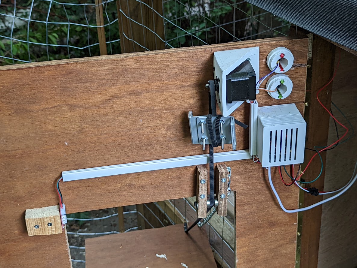
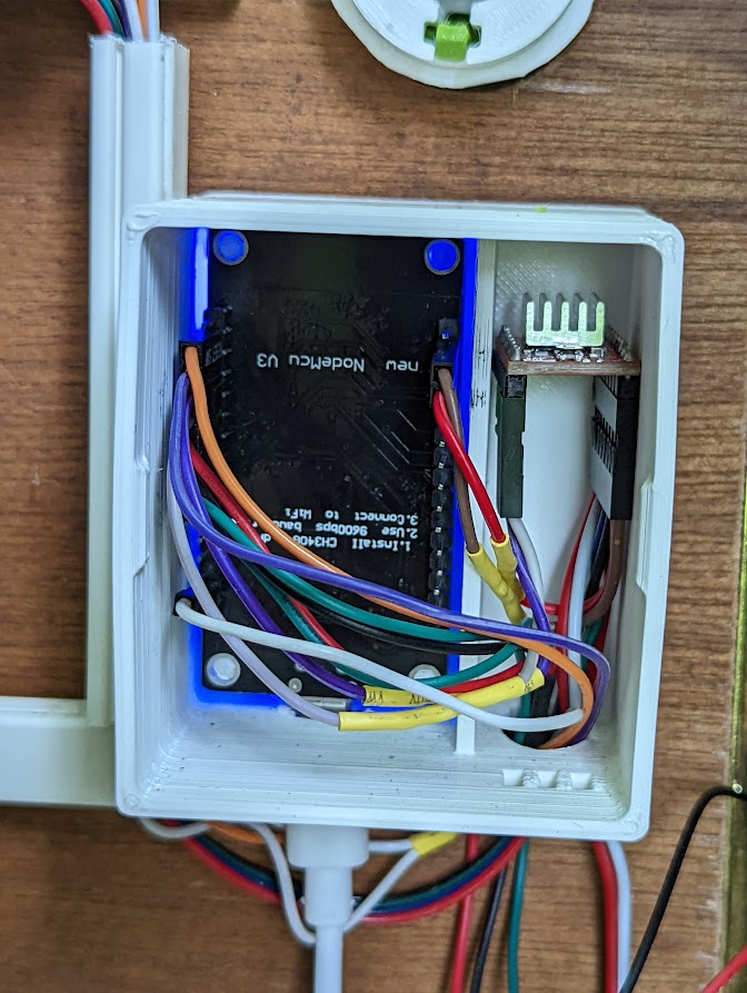
Wiring
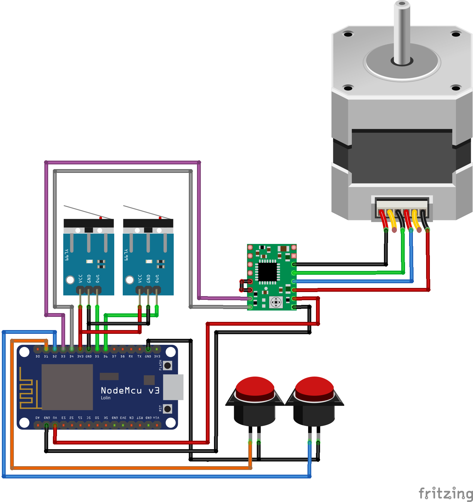 Here is the schema to connect everything to the NodeMCU.
The NodeMCU itself is powered via micro USB.
The A4988 driver is powered by the 12V 2A power supply and connected to the VMOD and GND pins. (Not drawn in the schema)
The stepper motor cable is connected to the A4988 driver. You need to connect phase 1 to 1A/1B and phase 2 to 2A/2B. Or 1 to 2A/2B and 2 to 1A/1B, this order is less important.
For some reason the stepper motor I used had the green and blue wires switched. So the phases weren’t wired correctly: 1A/2A and 1B/2B. Not a big deal, I just swapped them in the dupont connector.
In the schematics I used the (default) wiring order, I assume that this is correct for most motors and that mine was just a bit odd.
Setting the correct VREF value
It is important to set the correct VREF value on the A4988 stepper driver. The term VREF stands for voltage reference, basically the current provided from the driver to the stepper motor. To calculate the correct VREF, I want to point you to the detailed guide from all3dp. It is not very hard, but they explain it much better.
Setting the value too low and your stepper motor can skip steps while having it too high can cause overheating and damage the motor. Although our usage isn’t as precise/heavy as a 3D printer. So I can imagine that skipping a few steps or a (short) period overheating isn’t really a big issue. Still better to prevent this.
ESPHome YAML Code
It was a bit of trial and error to get it working, but in the end the chicken coop is working with the code below. Maybe that it could be done prettier, or maybe it even has some unnecessary code.
esphome:
  name: esp-chickencoop
  platform: ESP8266
  board: nodemcuv2

wifi:
  ssid: !secret wifi_domotica
  password: !secret wifi_domotica_key
  fast_connect: true

  ap:
    ssid: "ESP Config Chickencoop"
    password: !secret wifi_domotica_key

captive_portal:

# Enable logging
logger:

# Enable Home Assistant API
api:
  password: !secret api_key

ota:

stepper:
  - platform: a4988
    id: chickencoop_door
    step_pin: D3
    dir_pin: D4
    max_speed: 500 steps/s
    acceleration: 50
    deceleration: 100

cover:
  - platform: endstop
    name: "Chickencoop"
    id: chickencoop
    device_class: garage

    open_action:
      - delay: 100ms
      - stepper.report_position:
          id: chickencoop_door
          position: 0
      - stepper.set_target:
          id: chickencoop_door
          target: 2000
      - logger.log: "Chickencoop opening"
    open_duration: 20.0sec
    open_endstop: endstop_bottom

    close_action:
      - delay: 100ms
      - stepper.report_position:
          id: chickencoop_door
          position: 0
      - stepper.set_target:
          id: chickencoop_door
          target: -2100
      - logger.log: "Chickencoop closing"
    close_duration: 20.0sec
    close_endstop: endstop_top

    stop_action:
      - stepper.report_position:
          id: chickencoop_door
          position: 0
      - stepper.set_target:
          id: chickencoop_door
          target: 0
      - delay: 100ms
    max_duration: 15.0sec

binary_sensor:
  # Endstop Top / Door fully closed
  - platform: gpio
    name: "endstop_top"
    pin:
      number: D5
      inverted: true
      mode: INPUT_PULLUP
    id: endstop_top
    on_press:
      then:
        - logger.log: "Endstop TOP reached"
        - cover.stop: chickencoop
        - stepper.report_position:
            id: chickencoop_door
            position: 0
        - stepper.set_target:
            id: chickencoop_door
            target: 0

  # Endstop Bottom / Door fully opened
  - platform: gpio
    name: "endstop_bottom"
    pin:
      number: D6
      mode: INPUT_PULLUP
      inverted: true
    id: endstop_bottom
    on_press:
      then:
        - logger.log: "Endstop BOTTOM reached"
        - cover.stop: chickencoop
        - stepper.report_position:
            id: chickencoop_door
            position: 0
        - stepper.set_target:
            id: chickencoop_door
            target: 0

  # Manual open button
  - platform: gpio
    pin:
      number: D1
      mode: INPUT_PULLUP
      inverted: TRUE
    name: "Chickencoop manual opening"

    filters:
      # Small filter, to debounce the button press.
      - delayed_on: 25ms
      - delayed_off: 25ms
    on_press:
      then:
        cover.open: chickencoop

  # Manual close button
  - platform: gpio
    pin:
      number: D2
      mode: INPUT_PULLUP
      inverted: TRUE
    name: "Chickencoop manual closing"

    filters:
      # Small filter, to debounce the button press.
      - delayed_on: 25ms
      - delayed_off: 25ms
    on_press:
      then:
        cover.close: chickencoop
You can add it to the Home Assistant lovelace interface and it shows up as a garage door.

The residents
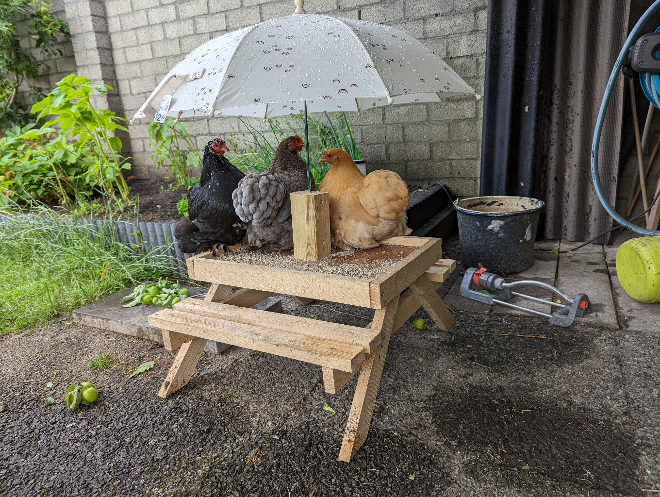
And finally… the residents!
Meet Els, Ans and Bep, here they are chilling at their chicknick table hidding for some rain under an umbrella.